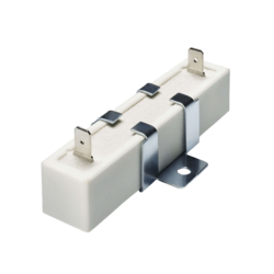
When an intermediate circuit is turned on, the capacitors are initially uncharged. As a result, they briefly act like a short circuit. Without current limiting, a very high inrush current can occur.
A properly sized precharge resistor limits this current. This allows the capacitors to charge in a controlled manner.
This article explains:
When a system with DC-link capacitors is turned on, the capacitors are initially uncharged.
For a brief moment, they behave electrically like a short circuit.
Without current limiting, the inrush current can therefore reach extremely high values.
The possible consequences are:
Proper calculation and sizing of the precharge resistor limits the inrush current.
This ensures that the capacitors are charged in a controlled manner before the main contactors close.
Three key values are required to calculate the precharge resistor:
The calculation is based on the time constant τ. It describes how quickly a capacitor charges through a resistor.
After 5 * τ, the capacitor has reached approximately 99.3 percent of its final voltage. In electrical engineering, this value is considered to indicate that the capacitor is practically fully charged.
Designing the resistance based on the time constant ensures that the capacitor is fully charged before the main contactors close.
The inrush current reaches its peak exactly at (t = 0), that is, at the very moment after power-up. It must not exceed the permissible limits of the contactors and fuses.
During the charging process, the resistor converts all of the absorbed energy into heat. This value is often a decisive factor in component selection.
• The formula: E = 0.5 * C * U²
At high DC-link voltages, the energy increases quadratically. This places high demands on the resistor’s pulse withstand capability.
If the system turns on repeatedly—for example, three times within 10 seconds—the heat in the resistor accumulates. For an initial estimate, the following applies:
P_avg = (E_sum) / (t_sum) = 3*E / 10 s
If the average power dissipation is too high, the component does not cool down completely between two charging cycles. The temperature rises from cycle to cycle until the resistor becomes thermally overloaded.
The calculation alone is not enough. The following specifications must be checked in the resistor’s data sheet:
The following system parameters are used:
First, the current limit yields the minimum allowable resistance:
The target value is derived from the loading time:
The recommended range is therefore between 120 Ω and 200 Ω. A lower value shortens the charging time but increases the inrush current. A higher value reduces wear on the contactors but prolongs the precharge process. Component tolerances must be taken into account during the final selection.
The resistor must convert 320 joules into heat during each precharge cycle. This value forms the basis for the pulse withstand test specified in the data sheet.
Accurate calculation values are a prerequisite, but no guarantee, for a precharge resistor that will function reliably over the long term. In practice, the physical properties of the component determine whether it can withstand actual operating conditions.
The two most common challenges and their technical solutions:
Every precharge cycle generates a high amount of energy loss within a few milliseconds. This energy is initially generated inside the resistor. If the material cannot dissipate this localized heat quickly enough, hotspots form that damage the component before the heat even reaches the housing.
Solution: High pulse resistance is crucial. Wire-wound resistors can absorb very high amounts of energy for short periods without sustaining damage. This prevents thermal overload inside the component and enables a compact design combined with high load capacity.
If the system switches on repeatedly at short intervals, there is little time for cooling between two charging cycles. The residual temperature from the previous cycle adds to the new power dissipation. Over several cycles, the component temperature rises continuously.
Solution: The resistor must be rated for the average power dissipation (P) of the entire operating cycle. Adequate cooling at the installation site is just as important as the component’s rated value itself.
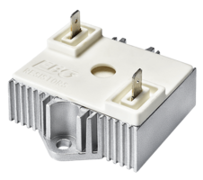
Miba Resistors manufactures high-performance resistors using thick-film technology. The components are designed for high continuous load and compact dimensions
